This realizes the NOT operation as follows: The circuit consists of a battery, a switch, and a lamp. The electrical equivalent circuit of the NOT gate is shown in the following figure. Where A’ or (A bar) denotes the complement of the input signal. The Boolean function of a NOT gate is given below. Boolean Expressionīoolean expression is a logical function that provides a mathematical relationship between the input and output of a logic. Input (A) Output (Y = A’) 0 1 1 0įrom the truth table, it is clear that the NOT gate performs the inversion operation by converting 0 into 1 or 1 into 0. The truth table of the inverter logic is given below. The truth table is a table of input and output that shows a relationship between them and is used to analyze the operation of the logic. It denotes a complement/inversion of the input signal. In the logic symbol, the bubble at the right corner of the triangle is called the inversion bubble. The basic logic symbol of a NOT gate is depicted in the following figure. Therefore, it operates as an inverter, i.e.

It gives a HIGH (Logic 1) output when its input is LOW (Logic 0), and it gives a LOW (Logic 0) output when its input is HIGH (logic 1). In digital electronics, the NOT gate has a single input and a single output. The NOT or inverter gate gives a HIGH (Logic 1) output when its input is LOW (Logic 0), and it gives a LOW (Logic 0) output when its input is HIGH (logic 1). In digital electronics, the NOT gate is a basic logic gate consisting of a single input and a single output.

If the input of the NOT gate is 1, then the output is 0, and vice versa. What is the IC number of NOT gate?Īnswer: Mostly used NOT gate IC is 7404 available in Dual-in-line package.The NOT gate is also known as the inverter gate. if the input is a “LOW” signal then it converts to a “HIGH signal” and vice versa. Q.No.1: Why NOT gate called as inverter IC also?Īnswer: The property of the NOT gate is to complement or invert the INPUT signal i.e. In this article, we have learned about the NOT gate symbol, truth table, transistor circuit, and NOT gate 7404 IC details and their minimum recommended settings. Recommended setting of NOT gate 7404 IC Conclusion The detailed datasheet of NOT gate IC is available here.

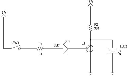
NOT gate IC working temperature condition is -55 degree Celsius to 125 degrees Celsius. The logic “HIGH” is considered if the voltage is higher than 2V and logic “LOW” is considered if the voltage signal is less than 0.8V. The MIN supply voltage is 4.5V required and MAX V cc should be up to 5.5V. Recommended operating conditions for NOT gate IC are provided in the following table. Recommended operating conditions of NOT gate circuit Inverter output pins are 1Y, 2Y, 3Y, 4Y, 5Y, and 6Y.Pin Number naming with 1A, 2A, 3A, 4A, 5A, and 6A are input pins.The pin diagram of NOT gate IC in different packages is provided below: SN7404 (D or N package) SN5404 (W package) SN54LS04 (FK Package) It is available in Dual In line package and Quad in line package. If the Switch (SW1) is open then the output load bulb is “ON” and if the Switch is closed then the output is “LOW”. The logic of the NOT gate is explained above as an electrical circuit. Thus the Output turns to the logic level as “LOW”. Vice versa when signal A is “HIGH” then the transistor is working and current flows from the R2 resistor to the ground and makes it a short circuit. In this case, the current flows from the R2 resistor and thus creates inverted output. If no voltage is provided from A Input signal transistor will be in an OFF state as no current flows the collector-emitter path. The Input Signal “A” is connected through the R1 resistor to the base of the transistor. NOT Gate Transistor Circuit NOT gate Transistor Circuit In the above simulation if the input signal is “LOW” or 0 then the output LED is glowing and when the input signal is “HIGH” or 1 is applied then LED remains “LOW” or off. The truth table of NOT gate can be checked in following simulation In vice versa, if the input is a “LOW” signal then the output becomes a “HIGH” signal. The truth table of not or inverter gate is follows A (Input)Īs we can see in the above table if the input A is “HIGH” not or the inverter gate complements the input and make it a “LOW” signal. NOT gate Symbol Boolean expression of NOT gate NOT Gate truth table Suppose the input signal is A and the output signal is Y so the Boolean expression of NOT gate represents as follows. If no “bubble” is available in the symbol then it works as a buffer gate. The “bubble” (o) represents at the end of the gate represents a complement of the input signal. Recommended operating conditions of NOT gate circuit.


 0 kommentar(er)
